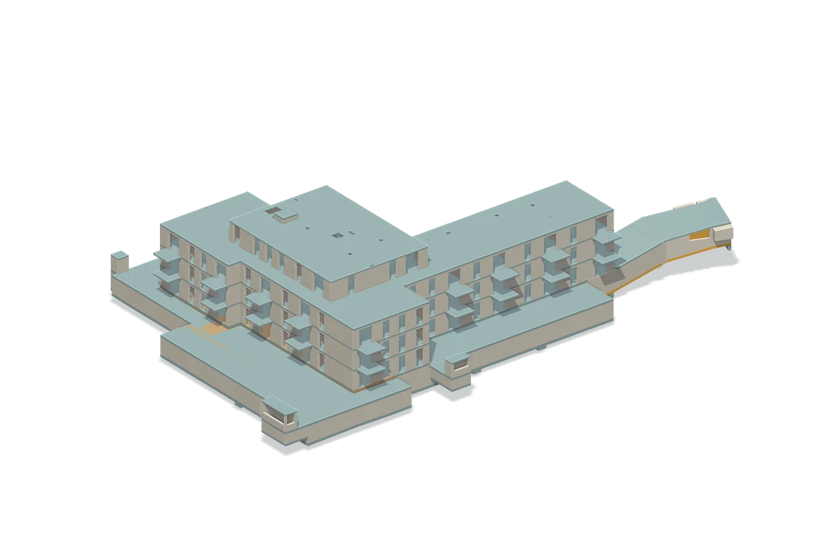
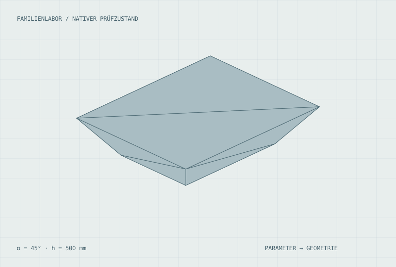
Existing structure & connection · tasks and process
WORK SAMPLE 02 / URBAN RENOVATION
Existing building and connections
First identify the element, type of drawing and floor. Then coordinate the interfaces.
01 / STARTING POINT
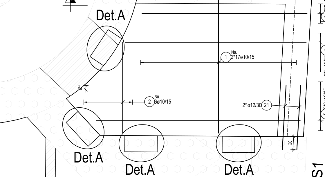
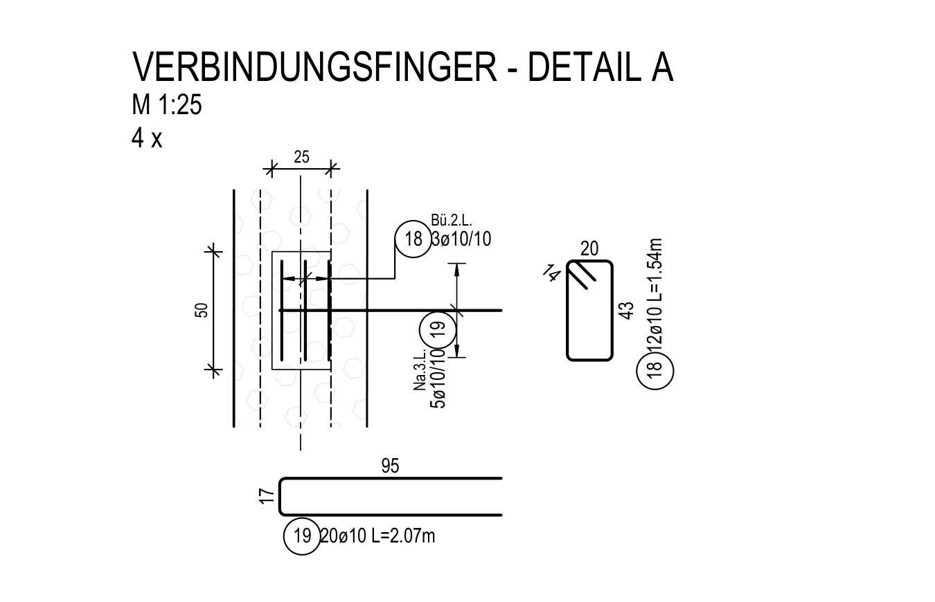
An extension meets existing elements. The base slab, bearings and narrow connection zones must remain clearly identifiable.
02 / MY TASK
I agreed the drawing scope with the team and updated the model and drawings.
03 / WORK PERFORMED
Incorporate new elements and agreed revisions into model and drawings. Treat external reinforcement drawings as a separate technical source.
04 / CHECKS & COORDINATION
I requested the missing reinforcement drawings for the roof-storey stair and the slab between the steel beams.
05 / DOCUMENTED RESULT
The formwork and reinforcement drawings show the connections. The consultant designed the reinforcement. I coordinated the documents with the design team.
Source & context
The drawings cover the foundation slab and ground floor. My reinforcement query concerns the roof-storey stair and slab.
Structural modelling in Revit, formwork drawings and construction details.Comparing drawing revisions and clarifying reinforcement drawing changes with the design team.Go to work sample
Qualifications & languages
Bachelor’s degree in civil engineering. German at B2 level, working knowledge of English, native Persian.
Earlier roles
BIM and CAD drafting
BIM modelling, CAD construction drawings, quantity take-offs and spatial coordination.
CAD drafting and team coordination
CAD drafting and team coordination; formwork and reinforcement drawings, Rhino visualisations.
Concrete technology
Concrete technology and quality control.
Contact
If your team needs help with structural modelling in Revit or formwork drawings, you can email me here. I’d be happy to walk you through my work on the ramp.
Using two revisions of a reinforcement drawing, I trace a change from the plan to the bar schedule.
How I work: I first check which drawing revision applies to the element. If the model and drawing differ, I discuss the discrepancy with the team and update both once we agree on the change.
I compared two revisions of the same reinforcement drawing. Both were prepared by the structural consultant.
Review the drawing revisionOriginal excerpts, bar marks and checking procedure
Work sample B · external reinforcement drawing
Changes to the bar schedule
Compare the same area in two drawing revisions. The bar callout leads to the old and new entries in the bar bending schedule. This drawing is from a different project than the ramp.
The original excerpts load when you open this section.
Reveal the change
I compared the same detail in two issues of the consultant’s reinforcement drawing: the original issue and revision A.
Mark 6 · 5 Ø10/15Mark 103 · 5 Ø10/15
Bar mark → bar shape → entry in the bar bending schedule
Mark 6: 9 → 4 bars · Ø10 · 3.75 m. New mark 103: 5 bars · Ø10 · 4.50 m.
Original mark / base revisionSame mark / revision ANew mark / revision A
Revision A keeps four bars under mark 6 and lists five longer bars under the new mark 103.
Source, role and limits
I compared the geometry in the consultant’s reinforcement drawings and recorded the differences for coordination.
Both drawing issues show the same location.
The bar schedule lists straight bars. On the original drawing, an adjacent dimension line crosses the bar sketch.
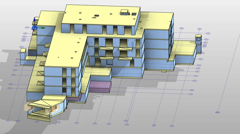
The IFC model contains 645 elements. At the foot of the ramp, you can compare the slab levels in the model with those on sheet 12.
My work and the source documents
My work
My initials appear on the formwork drawing. I worked on the model and drawings and coordinated changes.
Evidence
The geometry comes from the IFC model. My initials, H.ELL., appear in the title block of the formwork drawing on sheet 12.
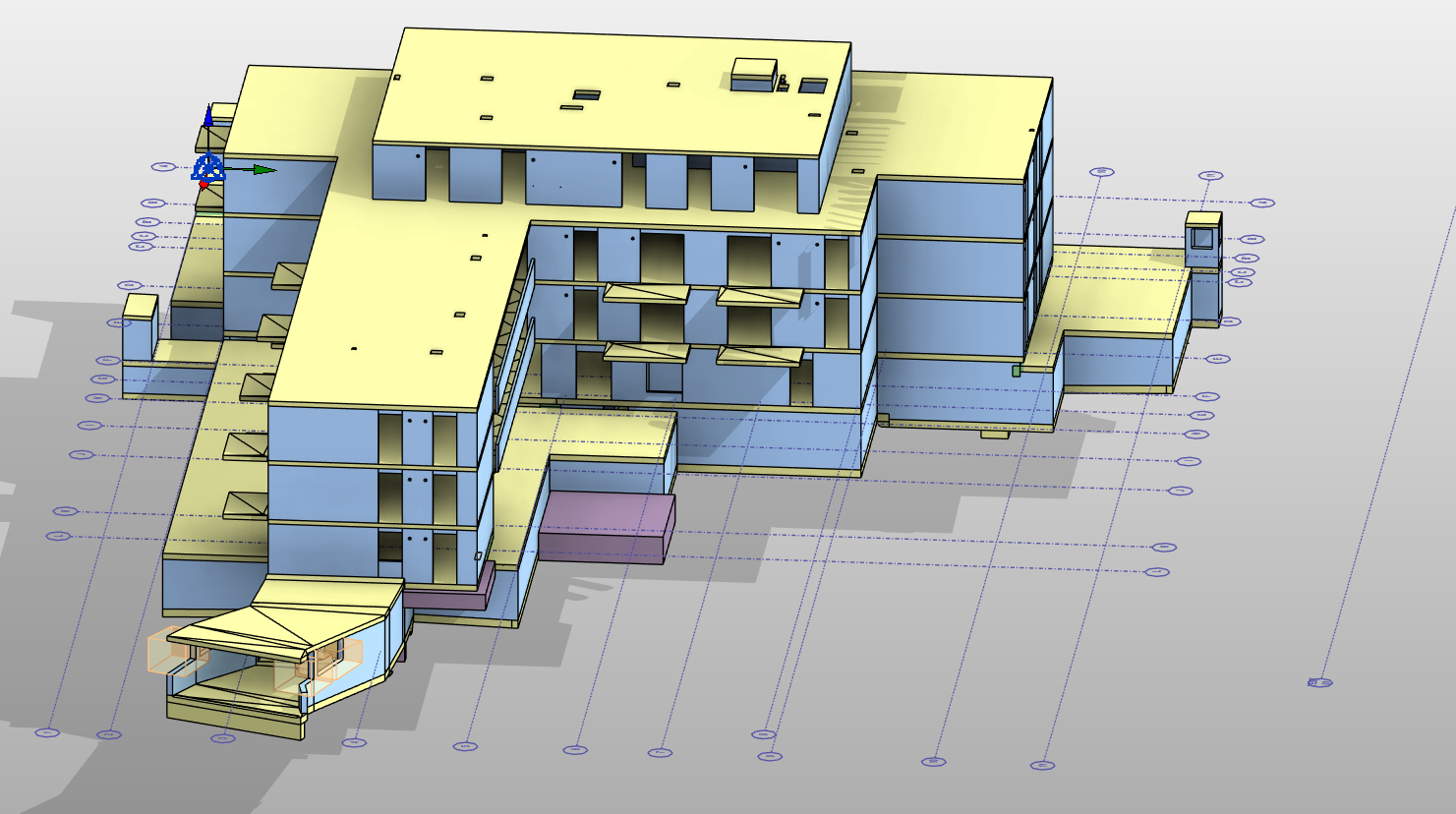
Review the model and drawings in your browser. Revit does not run here.
02 Revit / selection & properties
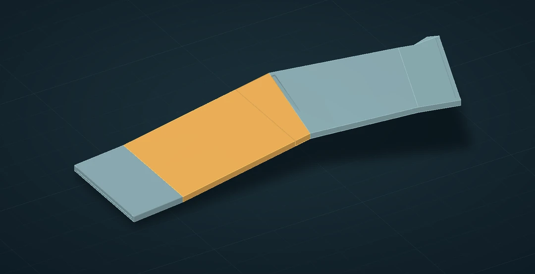
The ramp slab and its supports
The inclined ramp slab M-0246 remains visible together with neighbouring slabs and walls. The selection is preserved throughout the study.
Drawing note36 cmRamp foundation
ReferenceChecked locallyPlan & geometry
Die lokale Zuordnung ersetzt keinen vollständigen Modell-Plan-Abgleich. Modell und Plan tragen unterschiedliche Stände.
03 Revit / section
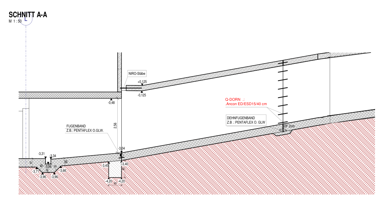
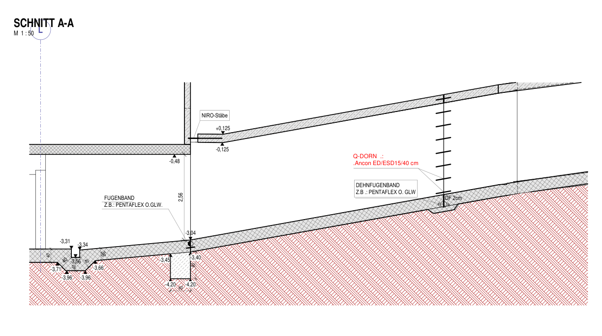
The connection in section A–A
The model is cut along A–A on sheet 12. The section shows the ramp and the adjoining elements.
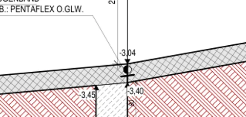
A–A is located in the model. The other sections are available as drawing extracts.Local result: Am Rampenanfang stimmen OK −3,04 m und UK −3,40 m überein. Die Zeitstände unterscheiden sich; OK??? / UK??? im benachbarten Anschlussdetail bleiben offen.
The cut edge shows the IFC geometry. Sheet 12 contains the formwork drawing.
04 CAD / original document
Plan and sections on Sheet 12
Sheet 12 · Foundation plan · Original excerpt
Local result: The outline and checked levels match in this area. OK??? and UK??? remain unresolved in the connection detail. The drawing as a whole has not been approved.
Lokaler Bezug zu M-0246 geprüft. Andere Bereiche sind damit nicht automatisch bestätigt.
05 Check / source comparison
Unresolved levels at the connection
Open / clarification required
The top and underside levels are still missing in the connection detail.
Some levels are missing from the drawing. The item stays open until a revised drawing supplies them.
Read local level comparison
This item compares the model with the drawing. There is no associated BCF issue, Solibri report or construction approval.
06 Dynamo / Python
Filtering elements by level
The Dynamo script checks Ebene Grundriss for E03, first on the element instance, then on its type if needed. This parameter was not exported to the IFC extract.
Original graph, source file & additional query
Original graph · four nodes / three connections
Code Block → IN[0]"Ebene Grundriss";
Code Block → IN[1]"E03";
↓ OUT
Watch / preview filter ruleNot run yet
Separater Datenweg: IFC-Datensätze → Geschoßzuordnung → Ergebnisliste. Diese Abfrage ist nicht der bereitgestellte Dynamo-Graph.
Ready. This check runs in the browser and makes no model changes.
Original graph & execution scope
The Dynamo graph has four nodes, three connections and a CPython3 rule. The browser query tests the filter on IFC data. Collecting elements, converting Revit parameter types and setting the Revit selection are operations in the original graph.
Ramp slab M-0246 is linked to the foundation plan on sheet 12. Section A–A lets you compare its levels. Other levels in the connection detail remain unresolved.
My contribution
I worked on the model and formwork drawing and checked the geometry. Structural design is a separate responsibility.
Still to clarify
A common approved issue, complete levels and the adjacent slab edge.
The opening belongs to wall M-0002 in the main building. Start with the wall, nearby elements and original opening. An adjacent element hides the opening in front view. X-ray or a longitudinal section reveals it.
My work and the source documents
Task
Change the position and size of the wall opening, then compare it with the existing opening.
My work on this example
I built this comparison to show how moving an opening changes the wall geometry.
Source
IFC4 · E00-FOK. The model identifies the wall that hosts the opening.
09 View / reference / dimension
How the wall opening is dimensioned
The plan and longitudinal section show dimensions to the opening edges and the base of the wall. Moving a dimension label leaves the geometry unchanged.
My work and the source documents
Initial geometry
1,100 × 1,000 mm · wall thickness 300 mm · bottom of opening 310 mm above the base of the host wall. Dimensions are calculated from the extracted model.
Scope
This view comes from the model. No corresponding drawing sheet has been identified. Editing limits apply to the geometry only.
10 Automation / sheet / result
The revised opening on the drawing
Activate the drawing view first. AutoAnnotate finds references and proposes dimensions. After you apply them, it reads back the recorded values.
My work and the source documents
Check sequence
Original → variant → analysis → preview → apply → read back. Invalid or outdated references yield no annotation.
Open point
RUK has not been verified as a project parameter. The separate documented family test with 500 / 290 / 300 mm remains unresolved.
Next
The export contains your review note. It leaves the original drawing and its approval status unchanged.
An additional filter uses IFC category and floor assignment. Its inputs differ from the original Revit rule “Ebene Grundriss = E03”.
Original graph and web adaptation
The original searches for “Ebene Grundriss” = “E03”, checking instance before type and trimming outer spaces before an exact match. The web version uses category and level from the supplied IFC. It adapts the rule to different data. Eight Python branch tests used a simulated host; the original .dyn graph was not run in Revit here.
Loading data. Analysis leaves the original model intact.
Family data from Revit
Four family tests in Revit
Select a family and compare two recorded states.
REVIT → GEOMETRY / SAVED STATE
Loading test states…
Geometry check results
The views show the test states recorded in Revit.
Development & testing
AutoAnnotate
Revit tags and dimensions in controlled steps: analysis, preview and read-back.
Native tags and dimensions.
Check text and dimension overlaps.
Flag missing parameters.
Documented local test: 1 tag and 2 dimensions. Read-back values: 7,250 and 4,735 mm. The RUK value in the log was incomplete; the test is insufficient for technical sign-off.
How the Revit API, Python and MCP fit in
The tool uses C#, WPF and the Revit API. I use Dynamo and Python for rule-based workflows.
Earlier independent AutoAnnotate test · W-001
AutoAnnotate / controlled preview
Choose a test case. The demo leaves project files untouched.
Independent lab · dimensioning algorithm
Dynamo / existing-structure graphics · web demo
→→
Choose a node or start the sequence.
DRAWING STANDARD
Line weights on the drawing
Review screen colours and output line weights separately. Distinguish visible, hidden and cut edges.
Linework and line weights on this drawing.
Project template
A structure for views, drawings and recurring settings, presented here as a working method.
View template
Apply rule-based display before manual overrides. Keep graphics and output traceable.
In the office and on site
The photographs show my workplace and slab reinforcement before the concrete pour.
Person and working environmentModel editing and a look at work on site
HOOMAN ELLYOUN / VIENNA
My work in the design team
I work with structural models and formwork drawings. When a connection is unclear in plan, I check the section and discuss the open question with the design team.
I build Revit tools for repetitive tasks, including dimensioning wall openings.
Revit · AutoCADModelling and drawing productionIFC · drawing revisionsREFERENCE AND COMPARISONDynamo · PythonRULE-BASED WORKFLOWS / DEVELOPMENTRevit API · MCPINTEGRATION / DEVELOPMENT AND TESTING
You can inspect the portfolio models in your browser.

 Find the level difference